

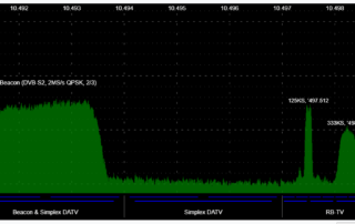
125KHz-channel up-converter to receive the Oscar 100 satellite with a DVB-S2 decoder
125KHz-channel up-converter to receive the Oscar 100 satellite with a DVB-S2 decoder. A 125KHz-channel up-converter handling six different symbol rates to receive Oscar 100 on DVB-S2 ATV, with remote tuning control via an infra-red remote control (of any kind) and frequency auto-complete. 1. PREMISE 2. CHOOSING FREQUENCIES 3. SAVING THE SIX CHANNELS ON THE DECODER 4. THE PLL 5. THE ANALOGIC PART OF THE PLL 6. THE DIGITAL PART OF THE PLL 7. PLL MANAGEMENT SOFTWARE - 80ch.ino 8.

Measuring the dielectric constant Dk of PCB substrates
Measuring the dielectric constant ε_r of Teflon, Polyester, FR4, G10, or FR4 with an RF generator and a good bolometer. The goal is to measure the dielectric constant ε_r (ω), also called Dk, of a substrate with a good degree of accuracy. Several standardised systems can be found in literature, each with specific pros and cons. IPC (https://www.ipc.org) has 13 different methods to determine Dk and Df, also called tan(δ). ASTM (https://www.astm.org) and NIST (https://www.nist.gov) provide a wide range
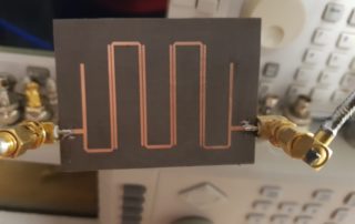
2310MHz Hairpin Microstrip Filter
2100-2400MHz Bandpass Filter The goal is to build a filter using the microstrip technique, resulting in low losses and a good shape factor. The project parameters are as follows: Zin, Zout: 50ohm Type: bandpass 2100-2400MHz Sub-type: hairpin Distribution of poles: Chebyshev In-band ripple: max 0.5 dB In-band RL: >18dB Attenuation at 1980MHz: >25dB Attenuation at 2500MHz: >25dB It should be noted that the narrower the passband, the higher the in-band attenuation; as a result, an attenuation of around 2dB
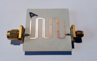
1200-1299MHz Microstrip Hairpin Filter
1200-1640MHz bandpass filter (flat within 0.2dB between 1200 and 1299MHz) The goal is to build a flat filter between 1200 and 1299MHz using the microstrip technique ensuring low losses, good shape factor and ability to cut frequencies around 900MHz. With the microstrip technique, the narrower the passband the higher the in-band attenuation; as a result, a “wide” filter was preferred – providing low in-band attenuation – but shifted upwards, so that the undesired band ends